
Back in April, I managed to get the five LED outputs sufficiently interleaved so that there would not be any noticeable delay between them. With the rest of the guitar mostly together, the bulk of the work left to do is now software based - ie getting the LEDs to do something fancy looking.

I'm not really a software person, but can see the benefit of building functionality up in stages. At the lowest level I need a function that can take LED data from an array and send it to the LEDs when it is called. Above that I need functions that fill these LED data arrays with a colour value, scroll them in a given direction or place characters in them. Above that comes the fun part of putting the building blocks together in order to achieve some blobs floating around or pacman chomping through the maze.
A few pointers
I struggle to understand pointers in C. I'm sure I've used them for years, but they never fail to trip me up. Unusually, MPLAB C requires some pointer operations to be in brackets to add to my confusion.
*ptr = 27;
would normally work, but for MPLAB C, it has to be
*(ptr) = 27;
It's fine once you know, but caused me a lot of headscratching at the start. Incrementing pointers doesn't require brackets, but when referring to the item being pointed to, it does.
Being sympathetic
When taking LED data and writing it to the five streams of LEDs, I did not want excessive array decoding to slow the process down in case it started blurring, smearing, flickering or becoming intermittent. I decided to keep the LED data array straightfoward at the expense of wasting a little storage space. The WS2812B devices need 24 bits each (8 red, 8 green & 8 blue), but the integer variables available are 8, 16 or 32 bits. Using 24 bits per LED struck me as a bad move as it did not correspond to a standard integer of any size, and it also did not leave me any contingency space in case I discovered something vital later...
I found some info about bitfields, so I used a memory-friendly structure that fits 32 bits, with an enable bit and seven spaces for anything that might turn up along the way. The normal RGB order was swapped for BRG so that the bits could be sent to the LEDs without any reshuffling.
struct LED_DATA_STRUCT_32
{
int blue :8;
int red :8;
int green :8;
int :7; // spare
int enable :1;
};
Another early thought that has worked well was to have foreground and background LED arrays. These are combined before passing the result to the LED update function. This layering can give a mild impression of depth or at least keep things separate when the going gets tricky.
The visual side of the software has evolved into three sections: displaying text, animated effects and transitions. The text display was conceived first alongside the first transition - scrolling left. Now there are around twenty animated effects, ten transitions and over sixty text phrases that get trotted out. The sequence of operation now is:
text - transition - animated effect - transition - (repeat)
There are also some hidden test modes that check the LEDs, plot various ADC values and a screen saver mode that looks like tiny bubbles rising to the surface!
I've got the power
During the software development phase I often had static LED patterns. Sometimes these would be on for half an hour whilst I tried to get the ideas in my head translated into code. During this time the neck temperature would rise by approx 25 to 30 degrees Celsius and is enough to change the neck relief!
The truss rod adjustment was carried out when the neck was at room temperature, but the compensation was too much when hot leading to a large amount of fret buzz. My working theory is that the acrylic f-board provides a certain level of additional neck stiffness, but as the temperature rises, its contribution reduces.

To combat this effect as much as possible, the neck compensation was reduced to an acceptable minimum, but the majority of the improvement in neck stability is from LED power reduction. All the effects were adapted to use 1/2 or 1/4 power where possible, especially when more than half the LEDs are on. Fortunately the LEDs are very bright on full beans even through smoked perspex, so this also helps cut down the glare and allow standard phone cameras to take pictures without completely saturating.
Effects
Once the bluetooth link has been established the mode changes to auto so that all effects can be called up. Other modes can be set manually, again using the bluetooth comms link.
The effects are numbered in pretty much the order they were written in and are described below.
1 - user text (entered by bluetooth link)
2 - preloaded text
Both text effects are run from the same function, the only difference being the source of the text phrase. During this stage the bluetooth comms link and message passing protocol had to be constructed as well as scrolling left and right and even defining a variable width character set. A hue function was also written to take a colour wheel value and convert to red, green and blue LED values.
3 - fret dots
Fret markers are quite a normal feature on most guitars. Some are just dots, some are more impressive blocks, ramps or crosses. The LEDs are fixed to the PCBs, but with a good choice of grid (some time ago!) and careful placement, the majority of fret marked positions line up fairly well. Once these had been identified, a variety of fret marker shapes and cycling colours are possible.
4 - balls
Bouncing balls uses floating point variables so that the balls glide effortlessly instead of stepping from one LED to the next. Slightly reminiscent of a lava lamp, but warms up quicker!
5 - comets
Comets was an accident. It uses the same function as balls, but was supposed to only give the outer perimeter. It didn't look too bright to start with, so the deleting at its old position was removed and replaced by a gradual fade out. This allowed the circular outline to create a pleasing trail.
6 - zig-zag
I wanted to do a scramble / defender style effect, but was still finding my way. I made a basic zig-zag terrain for an imaginary spaceship to fly through. The separate foreground / background layers were used with one zig-zag on each. They are colour cycled, scrolled and faded separately which creates a nice psychodelic feel. Hip & groovy man!
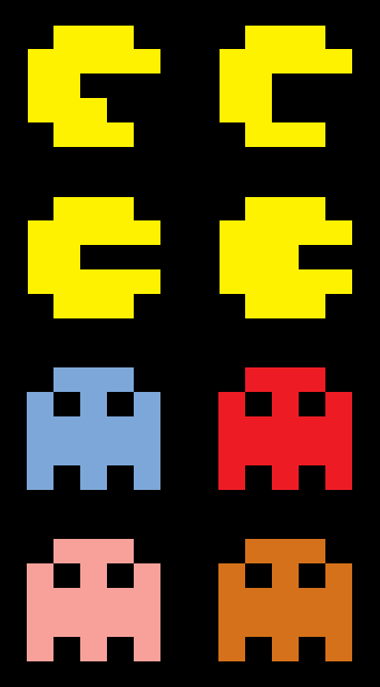
7 - pacman
The original moonbassalpha had a pacman theme. This was around 10 years ago and was my first bass build. It's still going strong :-)
With 80 LEDs across and 5 LEDs high, the 'screen' is not really the right shape for a pacman maze. On the other hand it is quite wasteful driving a whole screen when the pacman is the only bit that is important!

How many idiots does it take to paint a fence?
100!
1 to hold the brush still, and 99 to move the fence up and down.
We've all heard this joke before, but this was a lightbulb moment for me. 'PM' is fixed at the centre and the maze moves around. PM, the ghosts and all maze features are based on 5x5 LED characters.
To ensure that (human) eyes can track the maze movement, everything is moved one dot (height / width) at a time, in other words it takes five moves for the player to move one character sized space. This gave some tricky arithmetic when calculating relative positions of all the main players to see if PM and any of the ghosts meet.
Pacman sometimes shows the score, and sometimes doesn't. The effect looks better without the score, but with the numbers, the gameplay can be appreciated more. The game continues until PM bumps into a ghost.
8 - space journey
Space journey uses single point perspective to simulate a flight through, err, round multicoloured asteroids. Looks better from a distance, but in space that shouldn't be a problem ;-)
9 - kaleidoscope
Nice, simple and effective. Random chevrons are produced in the middle, and scrolled out to the edges. It reminds me of the shapes produced by a kaleidoscope that I had as a child.
10 - string bean
This obscure name is really just good old fashioned 1970's sound-to-light. A feed from the pickups creates an envelope signal which is connected to an ADC input. When the strings are played, the filtered output is converted into size / colour pulses which are scrolled across the fboard.
11 - tetris
This was another brain bender. Making blocky shapes and scrolling is ok, but working out the profile of where they might land and the best way to rotate them is not as easy as I hoped. Filling up the screen up takes a couple of minutes, so this runs for a bit, stores the info and then next time it picks up where it left off.
12 - running man
I must have watched a cartoon when I did this! The idea is that a man walks left to right and then gets chased back by something. Currently the chaser can be other men, a pacman, a ghost, a car, a spider or a snowball increasing in size. The spider needed to move in a particularly menacing way (in my mind).

13 - barrels
I thought about the donkey kong game, but this was as far as I got. A barrel rolls down red and blue inclined planks. No gorilla though.
14 - cells


The idea of growing cells continually splitting themselves in two was the basis for this one. I did not realise, but this is known as binary fission
The single cell splits into 2, 4, 8 and eventually 16 parts (as these all divide nicely into 80 LEDs and 32 does not).
15 - aztec
I like the idea of weird heiroglyphic symbols put together like a sort of secret message. These symbols rotate up and down and colour cycle to make sure that nobody can crack the code. Well, I can't anyway...
16 - fruit machiine
Three wheels, each with eight different fruits on them. The wheels are triggered from different positions, run at different speeds with different friction coefficients to keep it interesting. Occasionally all three match, but there is no coin tray for the winnings yet, so I've got to be content with a moral victory only.

17 - driver
Another dabble with perspective. I used some online help for this one.
It really needs a taller screen to look more effective, but it gives drunk people something to puzzle over.
18 - scramble / defender
After the first zigzag effect, I tried again. This time it went swimmingly well. Like pacman, the main space fighter ship is more-or-less central and the terrain moves up and down whilst scrolling past. The space fighter has a laser cannon and can blast holes in the landscape!
19 - diamonds are forever
A coloured-growing-shape-with-fade sort of pattern. Allows spectators to chill out after some of the more intense effects.
20 - streetlife
The thought here was a frogger style game - trying to cross the road without getting squashed. Again, due to the screen proportions, there wasn't any room for pavements so it is just a plan view of a dual carriageway. A bit of nous had to be used to allow vehicles to move from the slow lane to the fast lane and vice-versa without just crashing. They have to use their virtual mirrors in order to overtake and speed up! I am sure I have seen tail-gating and cutting-up too, I should have called it roadrage!
21 - fret dot halo
The fret dot effect is good, but quite static. To spice it up slightly this allows each fret dot to expand and contract at its own rate.
22 - centipede
The centipede game also needs a proper shaped screen. It wasn't going to get one, so I decided to split the game view into three sections - top, middle and bottom. The centipede worms its way from top to bottom, avoiding mushrooms. The shooter at the bottom fires indiscriminately at the centipede and the mushrooms and eventually it is all shot away. Sums up life in many ways...
23 - random squares
Does what it says on the tin. Difficult to add much more here.
24 - digger
I was determined to use the pacman 'engine' for something else. This chap is living underground, digging for diamonds and trying to avoid falling rocks.
test modes - just for me
90 - signal envelope
91 - random noise
94 - prbs15 (15 bit PRBS x^15 + x^14 + 1)
95 - prbs9 ( 9 bit PRBS x^9 + x^5 + 1)
97 - blank
98 - idle (when on stand)
99 - led test mode
But more importantly it makes dots jump around when viewed as a test signal!
Idle mode is entered automatically when the tilt switch detects that the bass is on a stand. It uses lop-sided filtering to ensure that entering idle mode takes several seconds whereas leaving it is much quicker. This avoids the effect disappearing when I hold the bass vertically (at the end of a rowdy number), yet kicks into life soon as it is picked up.

The LED test mode has already showed one LED has a problem with green, but other than that all is well. I will get round to replacing it one day...
List of transitions:
fade, sparkle dots, blank dots, sweep, scroll left, scroll right, scroll up, scroll down, monochrome fade, blur fade
All done and dusted
So far the Jellybean Bass has done 4 or 5 gigs and hasn't missed a beat. Hot plugging and unplugging does not cause any audible noises and now the neck heating is reduced, it does not change significantly during use.
I still have plenty of code space that could be used for more effects, but will need more inspiration for further eye candy.
95% of people are just happy to be watching a band in a pub with beer in their hand and do not notice anything unusual, but the other 5% watch in total disbelief. Guitars cannot do that...can they?


