During the tuner development I noticed another ESP32 module that has an audio codec on-board. A crazy idea of making a bass digital effects box appeared in my head and all that was needed was a bit of wiring up and a few lines of code...
After quite a bit of trouble getting the right ESP32 environment installed I eventually managed to get the starter projects running. The next stage was getting the codec to operate in loop-through mode to give a playground where I could mess about with all the samples any way I wanted.
Back in the real world, I decided a 350x100x50mm section of aluminimum U channel would be an ideal housing as it had been lying around in the garage for years. There was a hole already drilled about 60mm from one end so 3 footswitches symmetrically arranged seemed the best plan.
An advantage of software is the fact that nothing is completely hard-wired. Having 3 effects in series is plenty as long as they can be swapped about. The footswitches need to be individually identifiable so effects can be assigned to them easily. After a bit of sketching I decided to use colours and shapes to distinguish between the 3 effect channels and also light up when active. This would look much better than a 5mm LED and would not require any labels.
I had to make sure the relative sizes of the different shapes and colours looked about right so a temporary black paper cover was cut out and fixed on. I thought about countersinking the top screws that fix the perspex to the aluminium, but the cap-heads give it a solid industrial look which gives the top some additional interest.
An Inside Job
For the effect software running on the EPS32 module I pinned down the effects that I wanted: Flanger, Phaser, Chorus, Overdrive and Reverb. I've made a few distortion boxes before such as a Fuzzface and diode clippers, but most of the other effects were never possible with a handful of analogue components as they all require time delay elements.
Making these requires delving into circular buffers, comb filters, allpass filters and DDS oscillators then linking them up in the right way with a bit of trial and error. To get the maximum amount of processing into the time available, all signal computation was kept as fixed point. Decimal places always take longer to sort out...
Links for the keen...
Push The Pedal To The Metal
A guitar effects pedal is will be trodden on, tripped over and kicked about. Adding dozens of pots to allow adjustments to be made is only going to result in more things to snap off. Seeing as the ESP32 module is all singing and dancing (well, it has bluetooth built-in), the possibility of changing settings remotely seemed the way to go.
All effects, parameters and values are encoded into a single string which can be easily sent through the bluetooth channel. The ESP32 has the additional benefit of having dual cores, so as well as handling all the bluetooth comms, it can also do some preparatory work (ie floating point calcs) for various IIR filters that need to be primed once per transmission without taking any processing power away from the signal path.
Finished build
A 75mm x 25mm rectangular cutout was made in the side of the aluminium and a couple of 5mm perspex offcuts used to fill it. The ESP32 module is mounted on pillars to ensure its bluetooth aerial aligns centrally to this aperture to allow a good reception range. The veroboard on the left contains a 5V regulator for the ESP32 module and a 9V regulator for the input amplifier.
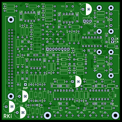
The afterthought piece of veroboard is required to reduce the common-mode noise from the ESP32 audio output. The both output channels are now used in anti-phase and fed into a differential amplifier which does a good job of keeping the ESP32's own squeals attenuated. This seems to be at its worst when bluetooth is active.
Using the black cardboard cutouts as a guide the final black vinyl covering was cut. Carbon fibre end plates were made from some offcuts which add to the industrial look.
The App
Initially the highly recommended Serial Bluetooth Terminal Android App was used to debug the ESP32 transmission strings. I settled on a simple ASCII based coding scheme that sends the effect type character, followed by a parameter character and finally the 16bit value. For example 'RM0032' will set the reverb mix to 50.
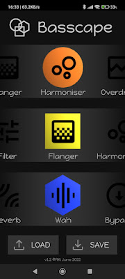
The Basscape Android app was created with AndroidStudio to allow the effects to be selected and swapped around. The main page ties in with the colours & shapes theme mentioned earlier. Effects are changed by moving them left or right. They are in a circle so after a few swipes you're back to where you started. If two positions show the same effect they are both greyed out. After each successful change a bluetooth message is sent to the EPS32 module ensuring the effects heard running are synchronised with the screen display.
To change parameters, the effect icon (in its coloured shape) is pressed which opens the effect page. This is a single app page, in the correct colour for the chosen channel and showing the correct parameters for the specific effect.
There are up to 3 drop-down menus and 6 slider controls arranged in 3 identically laid out sub-groups. Not all effects use all controls, so some can be left blank. After changing any control a bluetooth message is sent to the ESP32 module so that the effect update can be heard straightaway.
For Bluetooth comms to operate properly it has to be done separately to avoid making the main screens unresponsive. The Bluetooth comms is run 'behind the scenes' as a separate asynchronous task <https://stackoverflow.com/questions/9671546/asynctask-android-example>. This was another tricky section but makes the App / ESP32 interface really slick and effortless.
Effect and parameter storage is used so that when the App is re-opened it immediately reinststes the previous values and sends them to the ESP32 module. A final stage was providing Load and Save buttons so that effect settings can be stored to suit different occasions. Saving was a bit tricky in terms of file management, but loading was worse as once loaded the manually moved effect Recyclers had to assume the loaded-in values without human intervention.
Trying it all out & adjustments along the way
When the most processor intensive reverb setting was used with other effects there was a tendency for the processing loop to timeout causing stuttering. The sample rate was reduced from 44.1kHz to 32kHz and although sceptical, the sound even through full range speakers does not suffer unduly.
The initial setting up of the bluetooth link takes 2-3 seconds. This delays the main screen being displayed so a splash screen was created. Starting the App now shows the splash screen for 2-3 seconds and then the main screen is presented.
The wah effect was added quite late in the day. Without a position sensitive footpedal, the wah has to really be an autowah controlled by either the signal amplitude envelope or by an LFO. The (floating point) filter coefficients have to be frequently recalculated which requires juggling further computation between the two ESP32 cores.
Values are updated every two milliseconds. To avoid glitches, two sets of parameters are used internally in a flip-flop manner. In other words the 'V' parameters are used in the effect whilst 'W' is undergoing calculation. Once the calcs are done the effect switches to the 'W' parameters allowing the 'V' ones to be recalculated, and so on. Seems to work a treat in practise :-)
Soundclips
Still to do one day...
1. Chorus, Phaser, Flanger and Reverb - gentle filtering on outputs to reduce some harshness from the comb and allpass filters.
2. Chorus, Phaser, Flanger and Reverb - buffer purging so that no weird noises pop out when switched back in.
3. Harmoniser - autotune option to give nearest stepped note


