Showing posts with label esp32. Show all posts

Tuesday, 31 December 2024

Sequels

 I seem to have spent the last year or so doing upgrades to things that worked ok first time round but had room for improvement. 

Tuner 2

My class-D bass amp incorporated a tuner that used an ESP32 and a 1.5" monochrome display back in July 2022. This has been moved into my practise amp where it can carry on being useful. 

The revisited tuner still has three basic modes - Idle, Tuning and Active. The FFT based tuner algorithm has been largely left alone, but the visuals have all been updated and now use a 3.2" colour 320x240 LCD panel. This was made easier by using a driver to control the IL1931 chipset. The tuner view is now able to be used at the other end of a 6m cable without squinting!

Some of the visual effects took some time to get right. Most notable were the drawing-a-maze algorithm and controlling multiple bounces in breakout. The 3D cube principles were found online but fathoming out a way to avoid displaying occluded lines was left to me. 


Tuner visualisations


Speaker Measurement 2

A while ago I made an Arduino based speaker measurement box. It worked ok but the DDS was too wayward to give consistent results and the ADC sample rate a bit restrictive.

Seeing as the ESP32 A1S module worked well for my Basscape effects unit it seemed like a good starting place for another sequel. The built-in stereo CODEC channels are used to supply and monitor the AC signal whilst resistance measurements are handled by a separate DC coupled I2C ADC.


Topology 

Auto Balancing Impedance Measurement

In the earlier design, AC current was measured by a 3R0 resistor in series with the speaker, but for the new version an improved virtual earth or auto-balancing bridge method is used. The better separation of voltage and current signals along with higher sample rates allowed phase measurement too. After some number-crunching, sweep results are sent to the debug port for importing into a spreadsheet.


Speaker Measurement Box

Speaker Measurement LCD Results

Cerwin Vega MV-15B Impedance Plot

Monitor Audio RX2 Impedance Plot

Tannoy Reveal Impedance Plot

Coils of Wire

After some successful speaker measurements, the idea of changing its impedance range offered a way of measuring guitar pickups. LCR meters are ok for ordinary coils, but guitar pickups show resonance in the audio frequency range which renders simple testing at spot frequencies very hit-and-miss. The LCD shows the basic values - dc resistance, peak frequency & impedance and Q.

Pickup Impedance Measurement

Pickup Impedance LCD Results

Pretty Pictures

During development the values measured were sent to a logfile and later imported into a spreadsheet to make graphs. The ESP32 has WiFi capability so it was reconfigured to operate as a Simple Access Point. The measurement results were then sent directly as a web page showing the graph and important values.

Monitor Audio RX2 Speaker Impedance Plot

Monitor Audio RX2 Speaker Test Plot

Tannoy Reveal Speaker Impedance Plot

Tannoy Reveal Speaker Test Plot

...and pretty good for pickups too...

Vigier Arpege Neck Pickup Impedance Plot

Vigier Arpege Neck Pickup Impedance Test

Impedance is not everything

The response of a pickup to an electrical signal (measuring its impedance) is not quite the same as its response to a magnetic flux signal. There is a good degree of agreement, but it is not the whole story. Having re-read a few pages in Electric Guitar - Sound Secrets and Technology by Helmuth Lemme he describes a similar measurement system using a stimulus coil. Modifications were made yet again to allow an external coil to be driven to try this out. 

Vigier Arpege Neck Pickup Inductive Plot

Pickup coil switching and cable length options were tested individually and the plots combined using paint.net to show the results clearly.

Multiple plot - MoonBassAlpha Pickup Settings - Impedance

Multiple Plot - MoonBassAlpha Pickup Settings - Inductive

Multiple Plot - Second Bass Cable Lengths - Inductive
Multiple Plot - Second Bass Pickup Settings - Inductive

Sound Advice

This unit now gives a good idea of how a speaker or pickup will respond at different frequencies but there are still many other factors that can contribute to an overall lively or dull sound. It has helped remove some of the mystery and allowed me to make improvements to speaker cabinets and guitars with more certainty than flipping a coin.

A side effect of using the drive coil I was able to determine that some of my Jazz Bass pickups tested were actually split humbuckers (like Fender Precision split pickups, but in a single housing). Well, they are black boxes after all.


Saturday, 2 July 2022

Last Year I was Mostly...

Not got round to posting an update for a while, but over lockdown I was able to get some ideas out of my head and put some left-over parts them to good use. 


Driver Checking

This has nothing to do with the DVLA, but instead is a simple speaker measurement unit based on an Arduino with a separate AD9833 DDS which can give a sine shaped output. The Arduino controls the DDS frequency and its ADC allows speaker voltage and current measurement. The frequency is swept to find the points of maximum and minimum impedance. It's not the most accurate, but better than doing it manually, and gives reasonable results when compared to manufacturers data. This may allow me to find a new use for any unknown drive units hanging around...

Florence in a 4x10 cab

I have Celestion BL10-200X drivers in my 4x10 cab, here's the measurements of my 4 drivers (A, B, C & D) when I took them out with my assistant to repaint the front.


 Mfr   A   B   C   D

fs 73.0 61.3 69.2 65.9 72.5    Hz

Re  5.8  5.84  5.86  5.84  5.83   Ohms

Qms  3.58  3.31  3.09  3.13  3.12

Qes  0.56  0.46  0.51  0.49  0.54

Qts  0.48  0.40  0.44  0.43  0.46


Speaker D seems the closest to the published specs.


Here it is checking out an old 8" Soundlab 8LUX driver.


Driver test running

And the results are in:

fs 36.4  Hz

Re  7.15 Ohms

Qms  2.35

Qes  1.13

Qts  0.76


Driver test results fs, Re & Qts

Driver test results Qms & Qes


New Tunes For Old

In June 2021 I wanted to create a bass tuner to fit in my main amp. The Arduino just didn't have enough grunt for this, so I tried an ESP32 module and a 128x64 graphical LCD display.

Inside it uses the u8g2 display library with a modified Haichi Maru font to produce the smiley faces. The tricky stuff samples the signal at 4kHz, uses 512 point FFTs plus some filtering and topped off with Gaussian interpolation courtesy of the nice people at CERN. Such a name dropper! It's just a better way of working out where the real peak should be given the height of the ones either side.

I didn't want any buttons so the tuner just responds to a reasonably constant note. When the input signal is quiet it waits patiently, smiles and pokes its tongue out. 

Tuner - Idle

Tuner - Very idle

Once a consistent note is played it switches to the tuning view - the aim is to get the line horizontal, at which point the triangular markers are filled.

Tuning View

If it decides someone is playing (ie the notes keep on changing) then it cycles through oscilloscope, speaker and frequency views for amusement. Well it amuses me anyway.

Tuner - Oscilloscope display

Tuner - Speaker animation

Tuner - FFT display


LFO 

Over Christmas 2021 I decided to redesign the LFO section on my synthesiser that was built in 2007. It has worked well for several years, but when changing the duty cycle with ramp based waveforms, the frequency changes too. This limits the usefulness of the control as the interaction makes setting up awkward. My assistant took a keen interest.

Florence checking the synthesiser

In the centre position the duty was 50:50 as expected, and the current charging / discharging the main capacitor is equal in magnitude at that point. To put some numbers on it to help understand what's going on, the charging and discharging current could be +2mA and -2mA, equating to 1s rise and 1s fall to give a period of 2s or frequency of 0.5Hz. 

Moving the threshold from the mid 50:50 point to 90:10 gives +0.4mA and -3.6mA. The rise time will be 5 times slower at 5s and the fall time almost twice as fast 0.9s. Together these give a period of 5.9s which is a frequency of around 0.16Hz. It does give the right duty cycle, but the frequency is now much lower.

There is no easy way to keep the frequency and duty cycle independent, but there is a flakey analogue way that will vary with temperature and phase of the moon, so we'll go with that. Going digital in the middle of an analogue synth doesn't seem right...

Captain's Log (Amp)

To keep the same frequency, the above duty cycle needs to provide a charge current of +1.1111mA and a discharge current of 10mA. This gives a rise time of 1.8s and a discharge time of 0.2s. These still give an overall period of 2s (0.5Hz) and the right duty cycle. A reciprocal relationship is needed here (100/90 = 1.111mA and 100/10 = 10.0mA). Log amps here we come...

Log amp and antilog amp circuit blocks

From school maths (A * B) / C can be calculated using logarithms: Antilog( logA + logB - logC ). Once the log and antilog amplifier circuit blocks have been made, the rest is straightforward adding and taking away.  

Seeing as I was passing by I also improved the sine shaping and made the duty cycle able to be controlled by the other LFO.

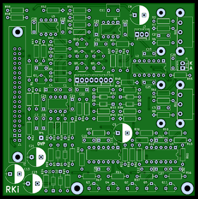
PCB artwork simulation

When controlling the VCF it can now cycle from wob wob wob to bow bow bow without changing the rate significantly. Sooooo much more usable than the old one.


Old and new LFOs