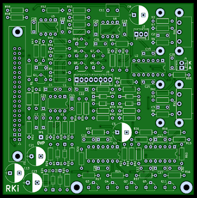
Not got round to posting an update for a while, but over lockdown I was able to get some ideas out of my head and put some left-over parts them to good use.
Driver Checking
This has nothing to do with the DVLA, but instead is a simple speaker measurement unit based on an Arduino with a separate AD9833 DDS which can give a sine shaped output. The Arduino controls the DDS frequency and its ADC allows speaker voltage and current measurement. The frequency is swept to find the points of maximum and minimum impedance. It's not the most accurate, but better than doing it manually, and gives reasonable results when compared to manufacturers data. This may allow me to find a new use for any unknown drive units hanging around...
I have Celestion BL10-200X drivers in my 4x10 cab, here's the measurements of my 4 drivers (A, B, C & D) when I took them out with my assistant to repaint the front.
Mfr A B C D
fs 73.0 61.3 69.2 65.9 72.5 Hz
Re 5.8 5.84 5.86 5.84 5.83 Ohms
Qms 3.58 3.31 3.09 3.13 3.12
Qes 0.56 0.46 0.51 0.49 0.54
Qts 0.48 0.40 0.44 0.43 0.46
Speaker D seems the closest to the published specs.
Here it is checking out an old 8" Soundlab 8LUX driver.
And the results are in:
fs 36.4 Hz
Re 7.15 Ohms
Qms 2.35
Qes 1.13
Qts 0.76
New Tunes For Old
In June 2021 I wanted to create a bass tuner to fit in my main amp. The Arduino just didn't have enough grunt for this, so I tried an ESP32 module and a 128x64 graphical LCD display.
Inside it uses the u8g2 display library with a modified Haichi Maru font to produce the smiley faces. The tricky stuff samples the signal at 4kHz, uses 512 point FFTs plus some filtering and topped off with Gaussian interpolation courtesy of the nice people at CERN. Such a name dropper! It's just a better way of working out where the real peak should be given the height of the ones either side.
I didn't want any buttons so the tuner just responds to a reasonably constant note. When the input signal is quiet it waits patiently, smiles and pokes its tongue out.
If it decides someone is playing (ie the notes keep on changing) then it cycles through oscilloscope, speaker and frequency views for amusement. Well it amuses me anyway.
LFO
Over Christmas 2021 I decided to redesign the LFO section on my synthesiser that was built in 2007. It has worked well for several years, but when changing the duty cycle with ramp based waveforms, the frequency changes too. This limits the usefulness of the control as the interaction makes setting up awkward. My assistant took a keen interest.
In the centre position the duty was 50:50 as expected, and the current charging / discharging the main capacitor is equal in magnitude at that point. To put some numbers on it to help understand what's going on, the charging and discharging current could be +2mA and -2mA, equating to 1s rise and 1s fall to give a period of 2s or frequency of 0.5Hz.
Moving the threshold from the mid 50:50 point to 90:10 gives +0.4mA and -3.6mA. The rise time will be 5 times slower at 5s and the fall time almost twice as fast 0.9s. Together these give a period of 5.9s which is a frequency of around 0.16Hz. It does give the right duty cycle, but the frequency is now much lower.
There is no easy way to keep the frequency and duty cycle independent, but there is a flakey analogue way that will vary with temperature and phase of the moon, so we'll go with that. Going digital in the middle of an analogue synth doesn't seem right...
Captain's Log (Amp)
To keep the same frequency, the above duty cycle needs to provide a charge current of +1.1111mA and a discharge current of 10mA. This gives a rise time of 1.8s and a discharge time of 0.2s. These still give an overall period of 2s (0.5Hz) and the right duty cycle. A reciprocal relationship is needed here (100/90 = 1.111mA and 100/10 = 10.0mA). Log amps here we come...
From school maths (A * B) / C can be calculated using logarithms: Antilog( logA + logB - logC ). Once the log and antilog amplifier circuit blocks have been made, the rest is straightforward adding and taking away.
Seeing as I was passing by I also improved the sine shaping and made the duty cycle able to be controlled by the other LFO.
When controlling the VCF it can now cycle from wob wob wob to bow bow bow without changing the rate significantly. Sooooo much more usable than the old one.


