Saturday 27 February 2021

The Finishing Touches

 Bouncing along

After a successful wind-up, the completed spring was slid onto the main tube. A 90 degree bend made at the bridge end allowed the coil to be anchored by passing the wire through the last fret position hole (drilled earlier for guidance). Each coil was nudged into position before fastening at the head end using a bicycle brake cable clamp-bolt. Finally the entire spring was glued to the tube with epoxy resin to prevent it wandering about. This was a bit messy and a fair bit of IPA was used in cleaning off the excess before it set.


Araldite securing the spiral frets


Tuners

Conventional closed gear tuners were used. These are normally fitted into the headstock which is around 15mm thick. The stainless tube is only 1.5mm thick and is curved! To get around this (quite literally) four circular aluminium spacers with OD = 30mm, ID = 16mm and length 24mm were sawn into 16mm & 8mm lengths then shaped to fit either side of the tube wall. 


Holding jig for the tuner spacers


It took a fair bit of whittling to match the tube shape. The tuners were then fitted to the tube using these spacers to sandwich it all together. The smaller convex spacer is on the inside. The small wood screw that normally prevents the tuners turning under tension is replaced with an M2 bolt that also passes through the main tube wall and clamps both parts of the shaped spacer.


Bridge

The separate parts of the bridge were assembled into fixed and adjustable sub-assemblies. The fixed part is bolted to the body tube and the adjustable part is clamped to this using M6 x 75mm bolts. This allows +/-4mm of height adjustment and a certain amount of sideways wiggle too. Angled holes were drilled into the taller end part of the bridge for the strings to pass through before sanding and polishing. 


Assembled bridge before string slots cut

The string grooves were cut into the saddle, and a horizontal groove cut underneath to allow space for the piezo pickup (see below). A drawback of this single saddle style of bridge is the limited intonation adjustment. I'm over it already...


Pickup

As this guitar is based on a tube, the strings cannot 'fan-out' from the nut to a larger bridge spacing without causing the action to increase significantly too. The spacing at the bridge is kept to be nominally the same as at the nut to prevent this increase in the action height and therefore requires a very small pickup too.

The smallest pickup I could find was for a Ukulele. Even this was too long so it had to be dismantled. The individual piezo elements measured around 7.5 x 1.2 x 1.2mm. 


Piezo pickup parts

Piezo pickup for a ukelele

Completed bridge with piezo elements


The first attempt sounded wrong using 3 elements. The middle element must have been too high causing The E-string end to be very weak. The centre element was removed second time around and with just two elements it sounded peachy! 


Altogether Now 


Tubular Bass - top


I'm very pleased with the spiral frets - they are no more difficult to play than straight ones. I deliberated over shimming the zero fret to make it slightly taller but actually got round to it. A truss rod was not required as the neck is an inherently stronger shape and shrugs off the string tension without showing any signs of curvature at all. A properly set up bass neck does actually have a slight bow to accommodate the string as it vibrates back and forth. This cannot be achieved here.


Tubular Bass - bridge


I've never used piezo pickups before and the sound covers the full audio range regardless of cable length. A common-place wound inductive pickup will have an electrical resonance that can be worsened by excessive cable capacitance. This can be caused by a long or a cheap cable. Above this resonant peak, which can itself add a bit of sparkle in the right place, the output drops noticeably reducing the amplitude of higher frequencies. The piezo pickup is in essence a capacitive pickup and additional cable capacitance makes very little difference. 


Tubular Bass - looking down on the tuners


The tonal character of a stainless steel tubular body, new strings and a piezo pickup system result in an extremely bright sound. This can be tempered by adjusting the playing position of the right hand to give a fuller sound. The same trick can be done on a conventional guitar but due to typical body shapes only a small range of playing positions seem feasible. On the tubular bass, there is no body or other points of reference, so the right hand can carry on up the fret board giving almost hollow synth-like tones.


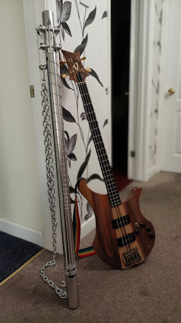
Tubular Bass and friends


Other than that, to be honest, it's a complete nightmare to play 😮 The string spacing is very tight for the right hand, and the picking hand has to reach round under the tube for the higher strings. 

Ergonomics were not that high on the list of important considerations.


Tubular Bass taken for a spin


It has stretched the concept of guitar construction in a new direction, but also reinforced that conventional guitars are good examples of incremental development. That being said, with a D-shaped tube and some welding, a more familiar neck and body could be crafted giving rise to an instrument that would have more universal appeal. 

But I like the prototype - it still looks like an exhaust pipe from a Lamborghini Murcielago 😊


Tubular Bass and Vigier Arpege


Friday 15 January 2021

The Spring Winder


The Spring Winder is based on the usual method of a rotating former and a wire dispenser moving along its length. For an ordinary spring, the wire would be moved at a constant rate, but for a fret-spaced spring it needs to be fast at one end and slow at the other. A linear actuator was obtained as they are popular in 3D printers. They are built from readily available extrusions with a stepper motor driven lead-screw. The spring length needs to be roughly 700mm, so a 1000mm actuator will allow some breathing space.

Aluminium Extrusion cross section

Linear actuator parts

An Arduino Uno was purchased as I really wanted to try one out! No additional programmer box or pricey software is required, just a USB A-B lead and a (free) download of the Arduino IDE. The built-in functions make pin operations straightforward and makes it a great introduction to programmable hardware.


After successfully blinking a few LEDs on and off, the main circuitry was developed to PWM control the winding motor and use a DRV8825 module to run the stepper motor. An LCD alphanumeric display was also added to show useful info. 


The winding former was estimated to be 30mm when using 1.8mm diameter stainless steel wire and a 50mm inside diameter. The winding speed was set at a fairly pedestrian 12rpm and the position of the winding former is monitored by a rotary encoder. 


The whole fixture was built on a combination of plywood and MDF measuring about 1200mm x 400mm x 45mm and uses pillow block bearings to constrain the winding former and a brass clamp to provide wire tension. The first winding motor tried out didn't have enough torque, so a larger motor was sourced connected to a chunky 36V/10A PSU. To negate the effect of loading on the motor speed, the PWM controller uses a small amount of current feedback. 

Winding a spring

Florence checking the spring winder

The main software loop takes the rotary encoder count, calculates* the new actuator position and sets the number of actuator steps so that this can be achieved. Using the micro-stepping facility of the DRV8825 module gave a nice round 100 steps per mm and worked up to a maximum rate of 8000 steps per second. If the quantity of steps are not completed within 30ms an error flag is set and the loop repeated anyway. The slow (~12rpm) winding speed ensures that this overspeed condition does not occur. This process is repeated until the windings are complete. 

Spring fully wound

Spring winder display


*The calculations use a simple linear ratio for the lead-in and lead-out at each end, and a more involved formula that comes from working out fret positions for the bit in the middle. 


distance = scalelength * (1.0 - 2.0 ^ (turns / -12.0))


An Unexpected Turn Of Events


Smart people will already have realised that turning the winding motor 12 times to get a whole octave of windings does not result in 12 finished coils! The ratio of spring ID to former ID had been overlooked. The spring is wound on a 30mm former, but when released (and yes, this was a scary bit) it rapidly returns to the more relaxed state of 50mm diameter. It is the same length of wire in both cases so the larger relaxed diameter has less turns. To correctly compensate for this it needs to rotate (50/30) more turns than I first thought. 


After this, I settled for 4 lead-in turns, 4 lead-out turns and 26 fret turns based on 50mm ID. This equates to around 7 lead-in turns, 7 lead-out turns and around 44 fret turns when mapped to a 30mm former. The 26 fret turns allows some freedom in choosing the best 22 (plus a zero fret). 


After several rounds of debugging it was ready to run. Winding the spring took around 5 minutes and apart from a bit of congestion on the lead-in, it nailed it first time! The video clip speeds up the action into just over a minute.


Doing The Rounds


In between working on the Spring Winder, other parts of the Tubular Bass also needed to be made. The nut and bridge assemblies are both made from aluminium, mostly 15mm thick, but the nut and saddle are only 6mm. To anchor these, 47mm discs are turned on a lathe** and fitted inside the tube. The visible parts of the nut and bridge are bolted to these through slotted holes to allow a certain amount of height adjustment but keeping things sturdy and rigid. 

Tubular bass - bridge parts

Tubular bass - bridge parts


Tubular bass - bridge assembly

**I don't have a lathe so I laid a benchdrill on its side instead. Each part was rough cut into an octagon shape with an 8mm centre hole, then turned lathe-style. It doesn't have quite the same bearing system as a proper lathe so there is more judder and it doesn't give a great finish but it's good enough. Don't try this at home - it makes a lot of swarf!

Dodgy machining practices


Monday 4 January 2021

The Steelworks

 An unexpected problem of this bass build was the complete lack of any useful edges or datum lines. Before any holes are drilled or cutouts are made, the tube needs to be marked out. This can't be done freehand, or with a ruler so I had to think outside the, um, tube. Fortunately a bit of spreadsheet magic enabled me to plot some graphs that I could wrap around the tube and use as cutting guides. Once in place it was time to fire up the angle grinder - not a tool I normally use when making guitars!


Headstock angle grinding template
The guide allowed the two cutouts for the headstock to be made and marked the tuner holes for drilling too. 

Headstock template in place

Headstock grinding

Headstock rough cutouts

Making holes in stainless with ordinary HSS drills is often less than successful, cobalt ones seem to fare much better. 


Fretwire?


Bashing fret wire into wood is quite satisfying. Bashing them into perspex as I have done on the last two builds is not great - it doesn't have the same give and one bash too hard could end up cracking the whole fboard. For the perspex fboards I had to make wider slots then rely on glue doing the rest. There has been one or two dislodged moments over the years, but on the whole they have lasted well. Cutting accurate slots on the stainless tube could have been an option, but I think it would look 'bitty'. Besides I had another daft idea that could only work on a tube...


Curly Wurly


Progressive rate spring

Wouldn't it be great to use a specially wound spring fitted snugly on the tube to act as frets. It would start off with a wide coil spacing and reduces each turn. Between frets 12 and 13, the coil distance would be half that between coil 0 (the nut?) and 1. I drafted out a spec, supplied the equations and sent it off to a couple of spring companies for a quote. 


The coil winding fboard approach had a couple of side effects:


1. the frets won't be conventionally straight (perpendicular to the neck), they will be angled

Dingwall guitars make basses with fan frets. I've never played one, but apparently they combine good tone with playability. As long as the frets under each string are accurate to a single scale length, it doesn't matter that an adjacent string has a different scale length. Using a coil spring for the frets should be exactly the same. To capitalise on the thicker-strings-needing-a-longer-scale concept, so I'll need to ensure the spring is wound in the right direction!


2. the frets will also be on the back of the neck

Mmm, I suppose they will, but I'm going to do it anyway


Meanwhile, the spring company replies came back. One wanted £250 + VAT just to develop a spring with no guarantees of success, the other just wished me good luck...


The sensible option here would be to make the design more conventional, cut nice perpendicular slots and glue individual pre-radiused frets in. So I decided to make a purpose built spring winder instead*. Boing said Zebedee!


*To be honest I did try winding a spring manually first just to see how difficult it was. Stainless steel likes to fight back so this prompted the spring winder to be pretty chunky. As can be seen from the pic, manually winding a spring results in a very irregular string spacing which is no use at all.

Useful info gleaned from this exercise was the diameter of the former on which the spring is wound. Empirical equations exist, but this application is a way outside the normal wire-diameter-to-spring-diameter ratio. Two or three trial attempts showed that with a former of 30mm, a finished spring ID of approx 49mm was produced which was ideal.


Prototype winding former